
Installation instructions for
Contact-Optima-Profile
Installation Instructions
Installation Instructions for Contact-Optima-Profilesusing profile no.
3100.4053 as an example
0
Tools required
Rubber scissors, Side cutters without a bevel, Screwdriver Torx T10
1
Cutting the profile to length
Total length of the switching strip minus 14 mm for the end caps (7 mm per cap)
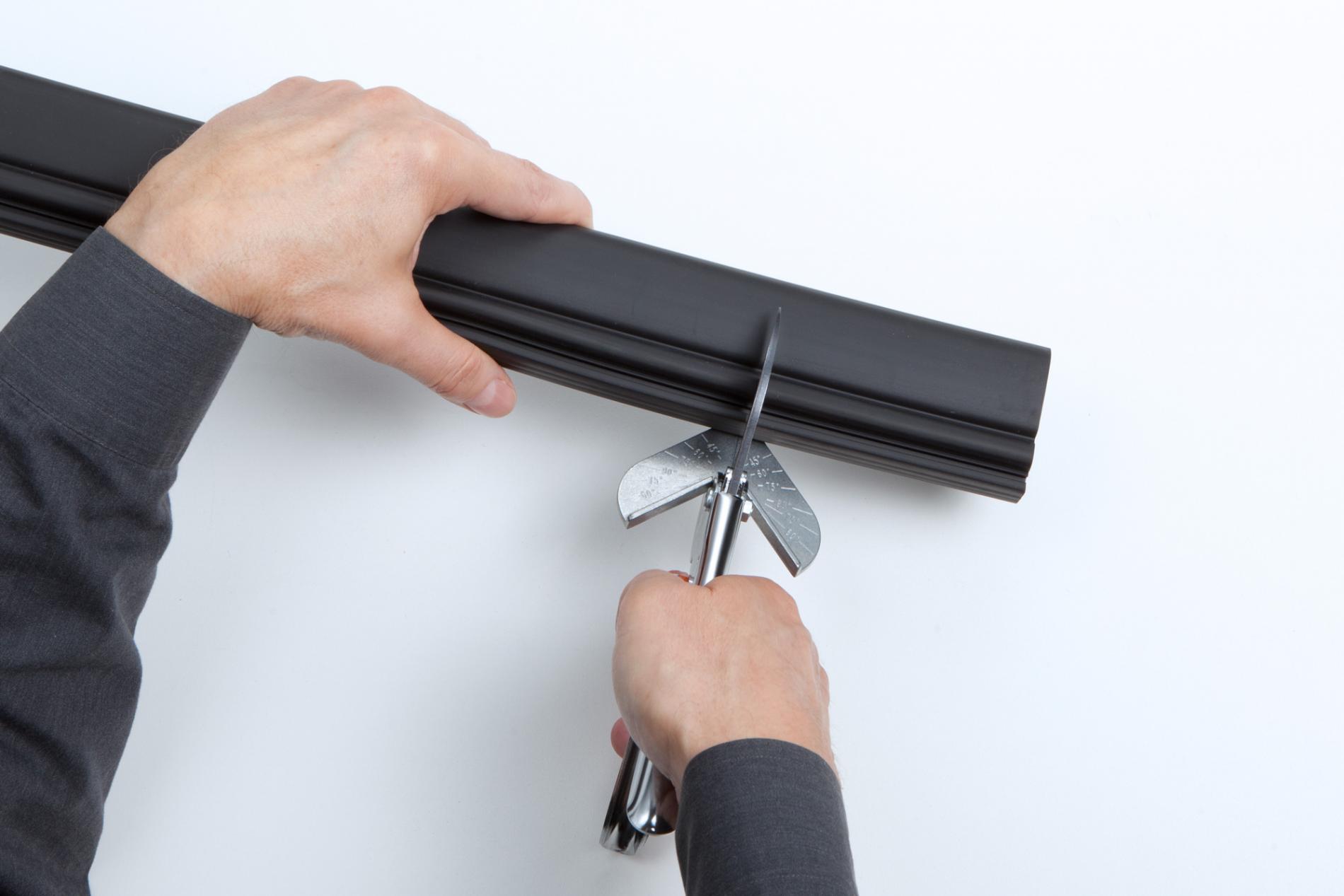
When cutting to size, ensure that the cut edges are straight, smooth and at right angles.
2
Preparing the profile
Make clean cuts approx. 9 mm into the right and left ends of the compensation chamber very close to the upper edge of the switching chamber. Make a parallel cut into the compensation chamber approx. 4 mm above each of the first cuts and cut out the scored strips.
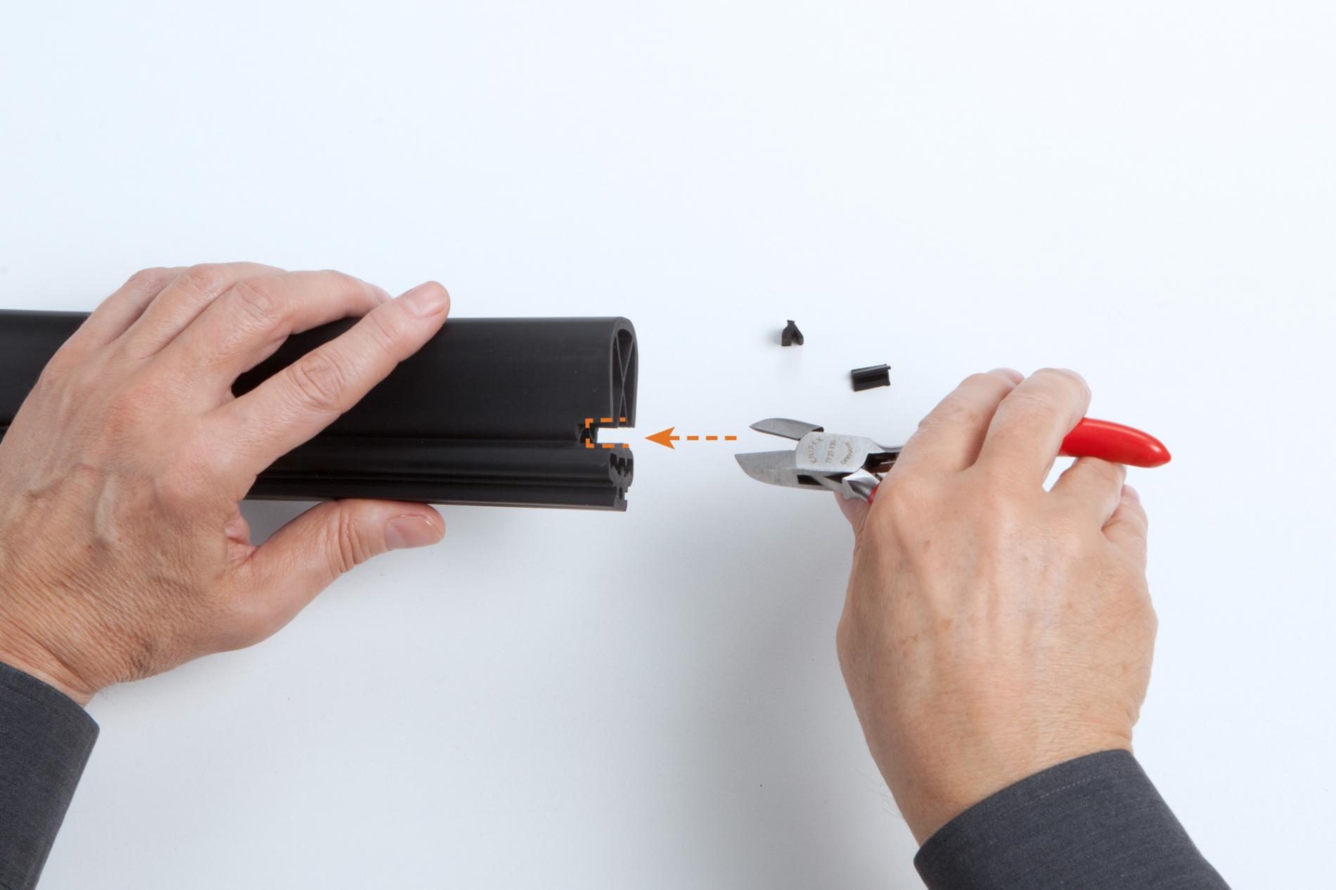
Note: Position the side cutter with the flat side toward the upper edge of the switching chamber in order to obtain a neat result.
3
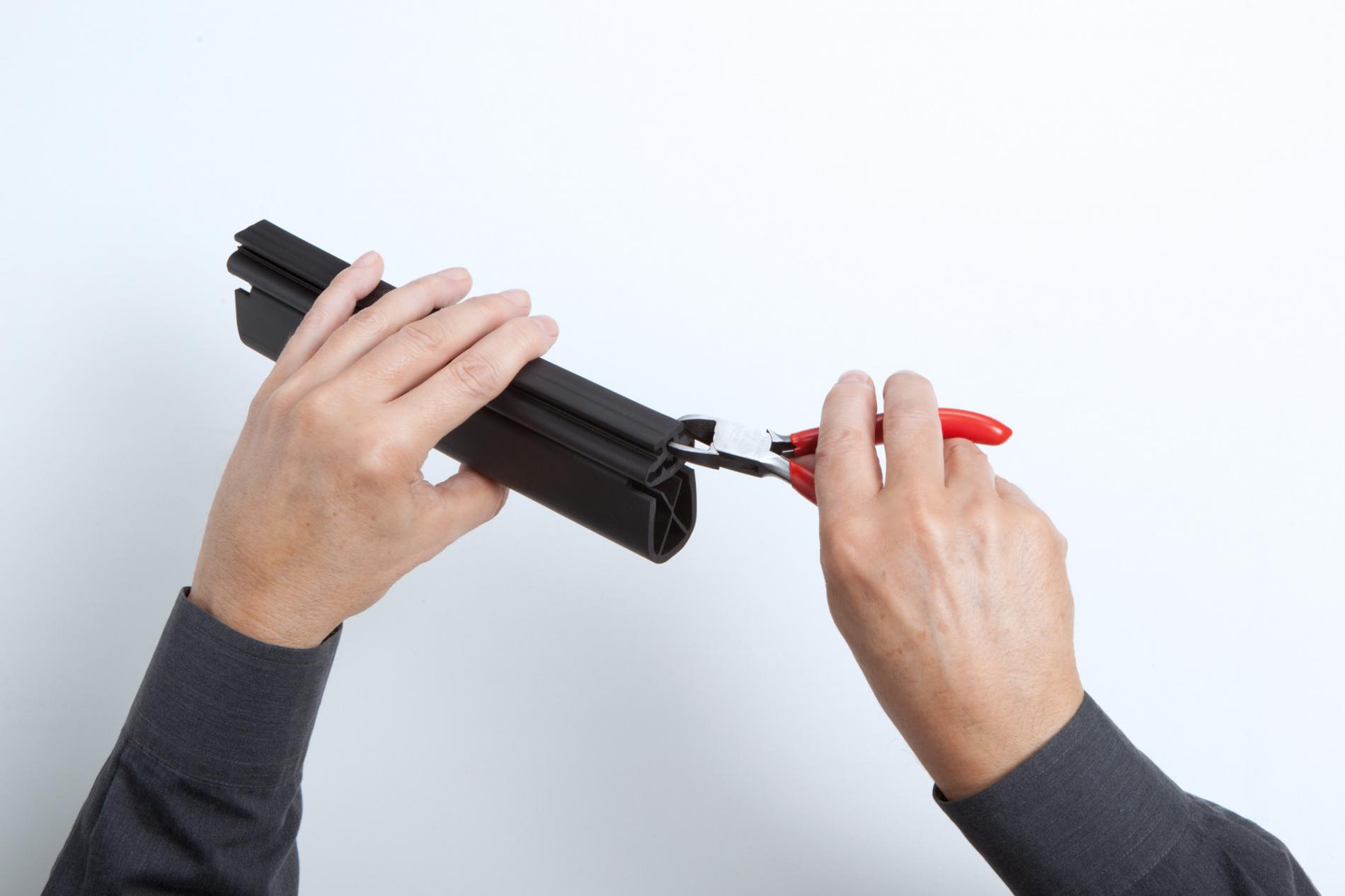
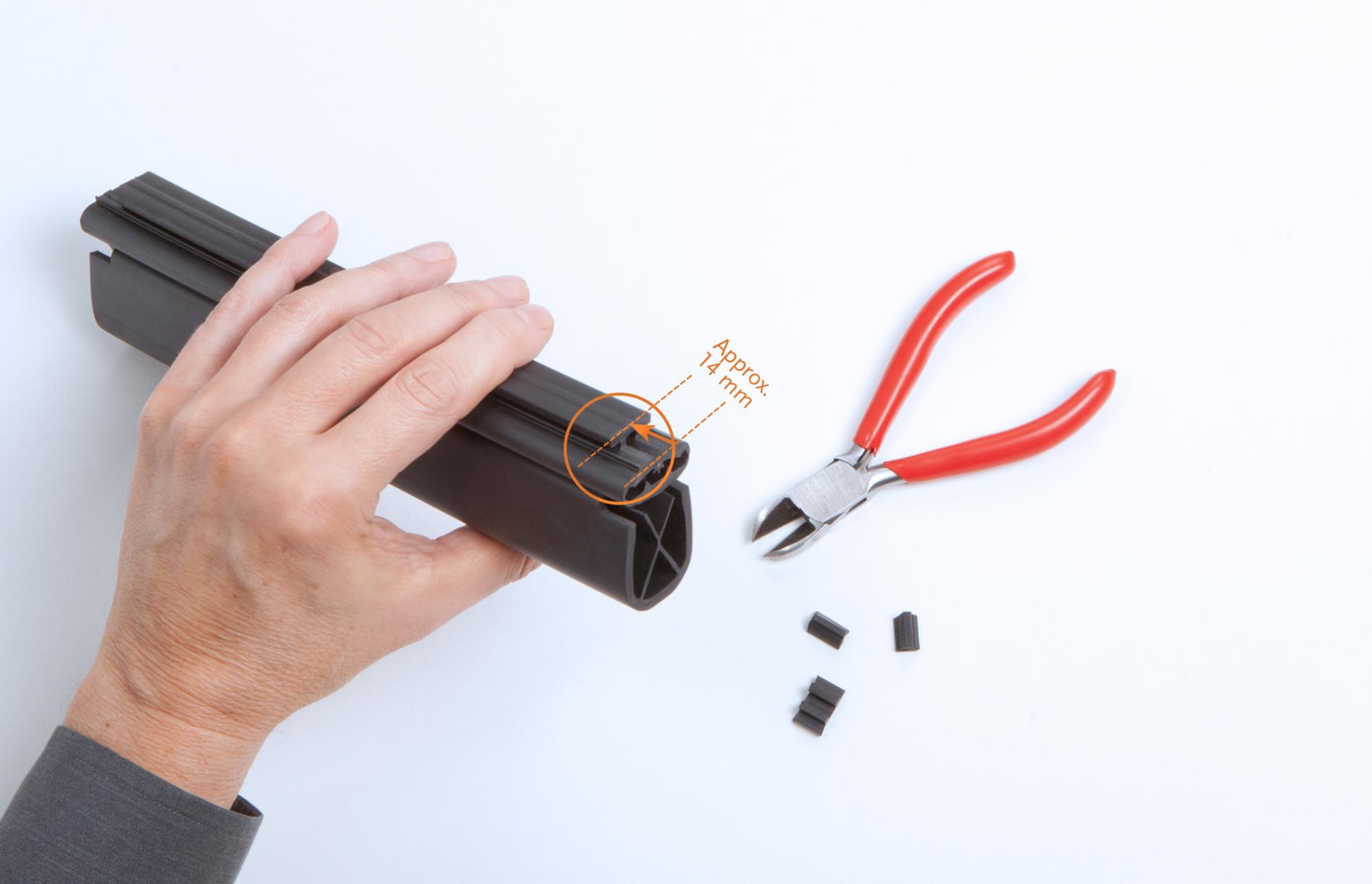
Shortening the foot to adapt to the length of the C-rail
Also make clean cuts approx. 14 mm into the right and left ends of the foot very close to the lower edge of the switching chamber and remove the cut sections.
4
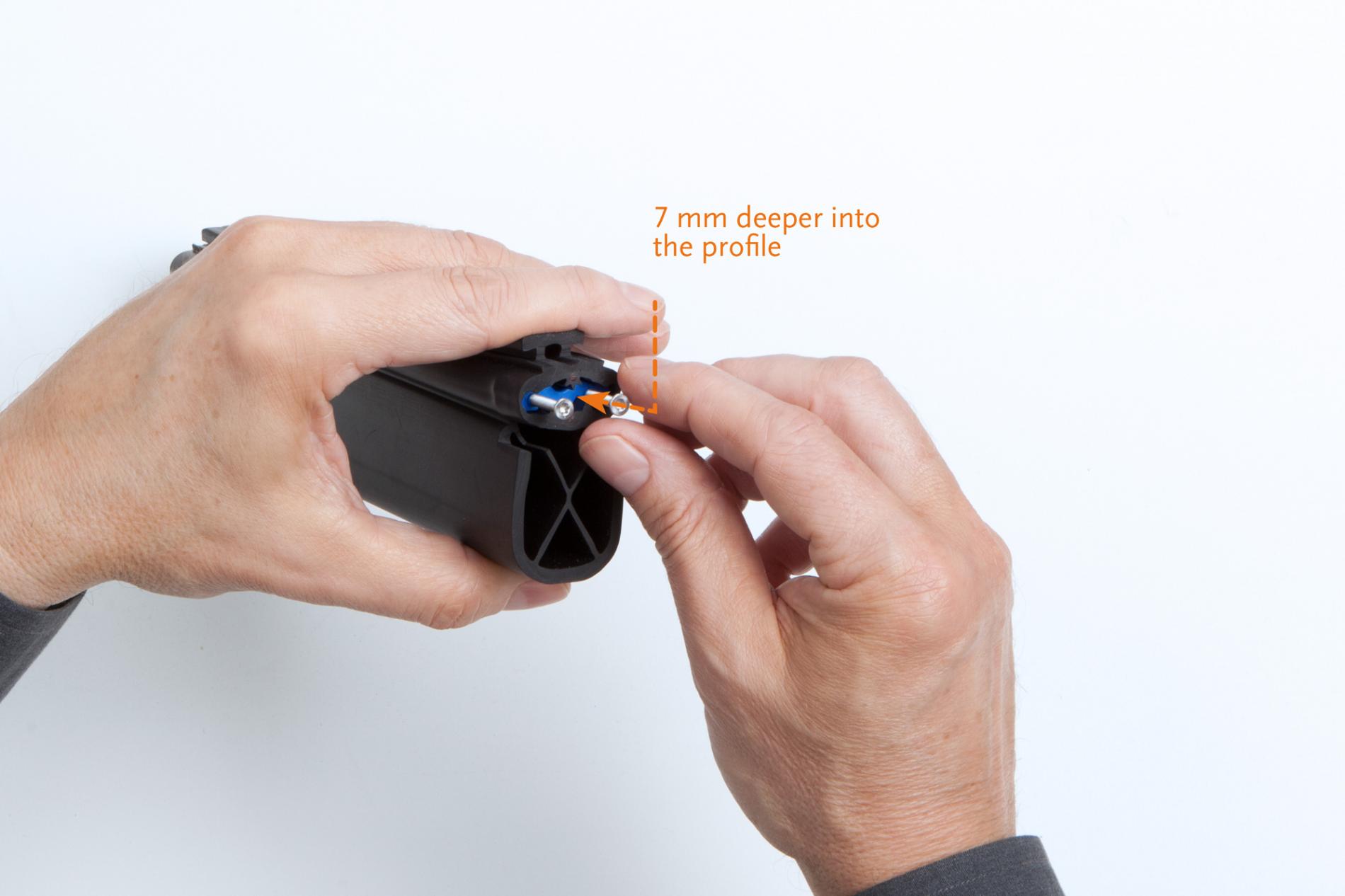
Preparing the crimp connection
Press down on the switching chamber and insert the blue inner section of cap into the switching chamber. Carefully push the inner section approx. 7 mm deeper into the profile.
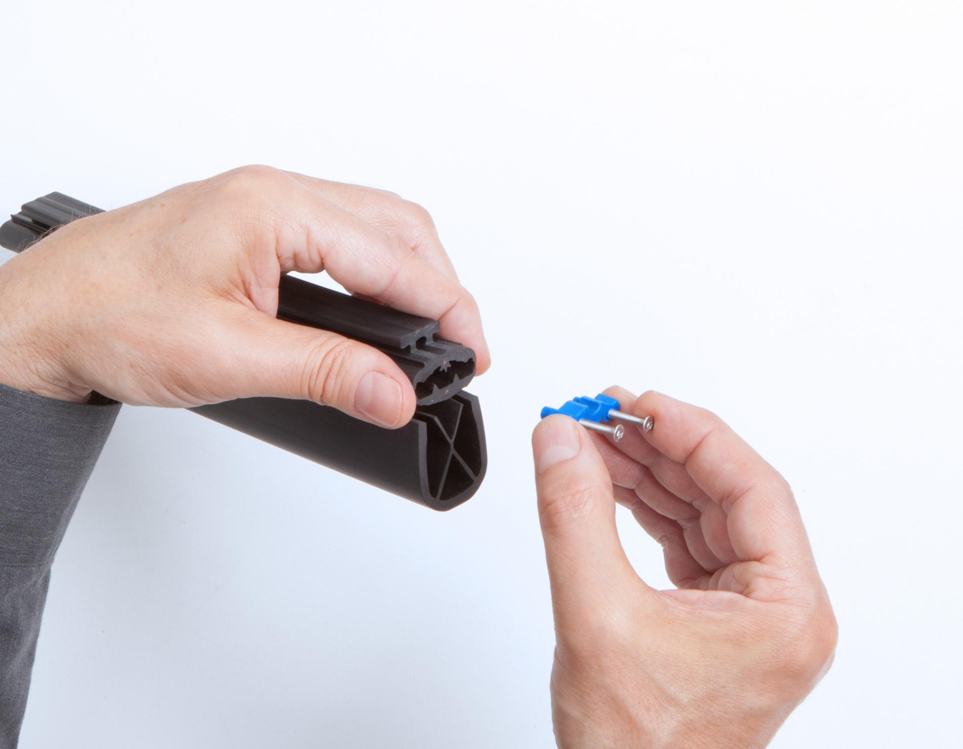
Note: The side with the cable bushings facing inward. If you use the screws as guides for inserting the end cap, remember to remove them again afterwards.
Do not insert the inner section of the cap too far otherwise the screws will no longer be able to reach the inner section after the end cap is attached.
5
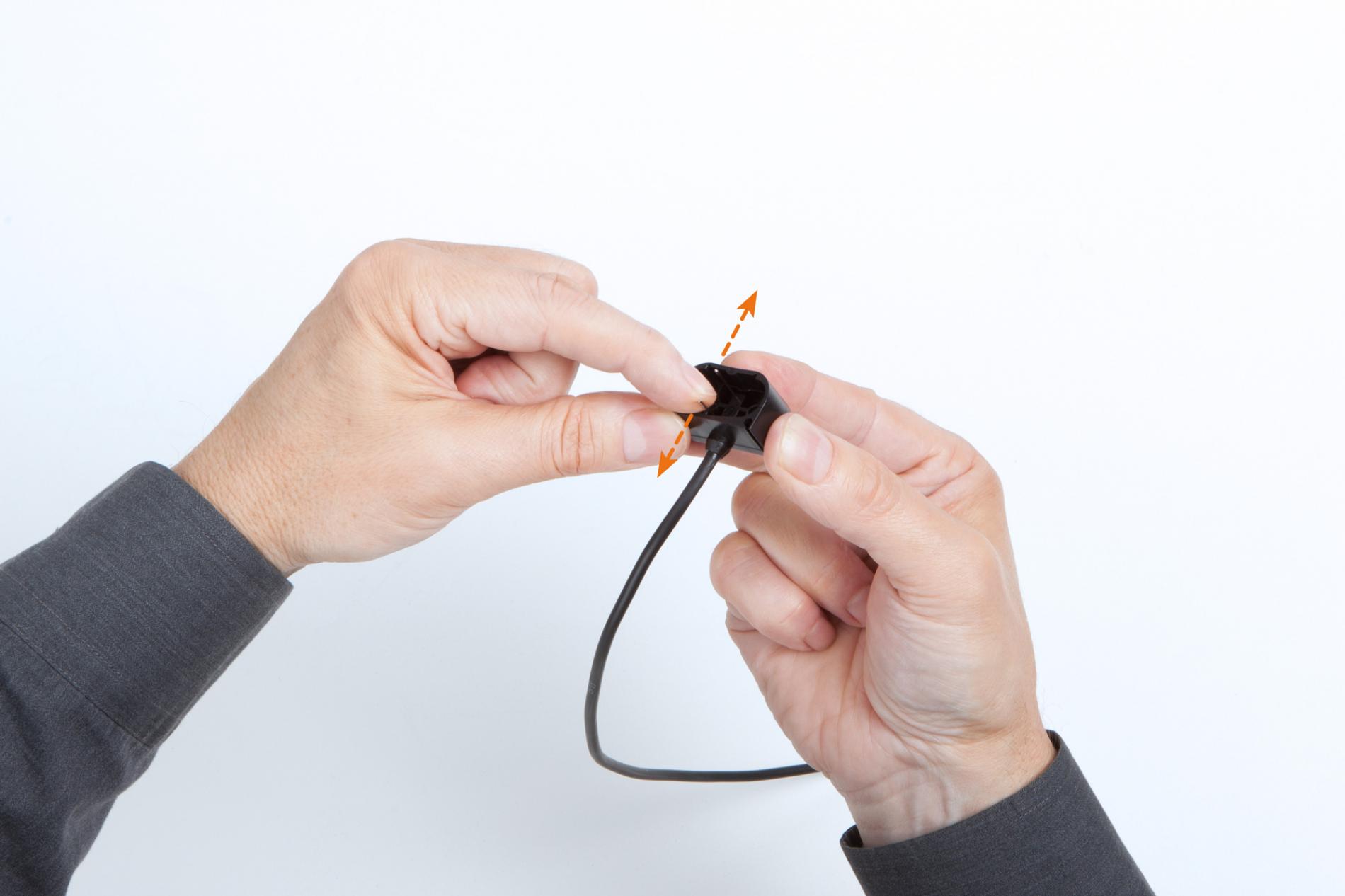
Preparing the end cap
Carefully spread the needles of the end cap 1 – 2 mm apart so they insert freely into the copper wires. Use the needles of the end cap to pre-punch into the centre of the top and bottom copper wires.
6
Fitting the end cap
Insert the end cap into the pre-punched copper wires while slightly compressing the height of the profile at the front. Push the cap onto the profile so that it fits squarely and encloses the profile completely.
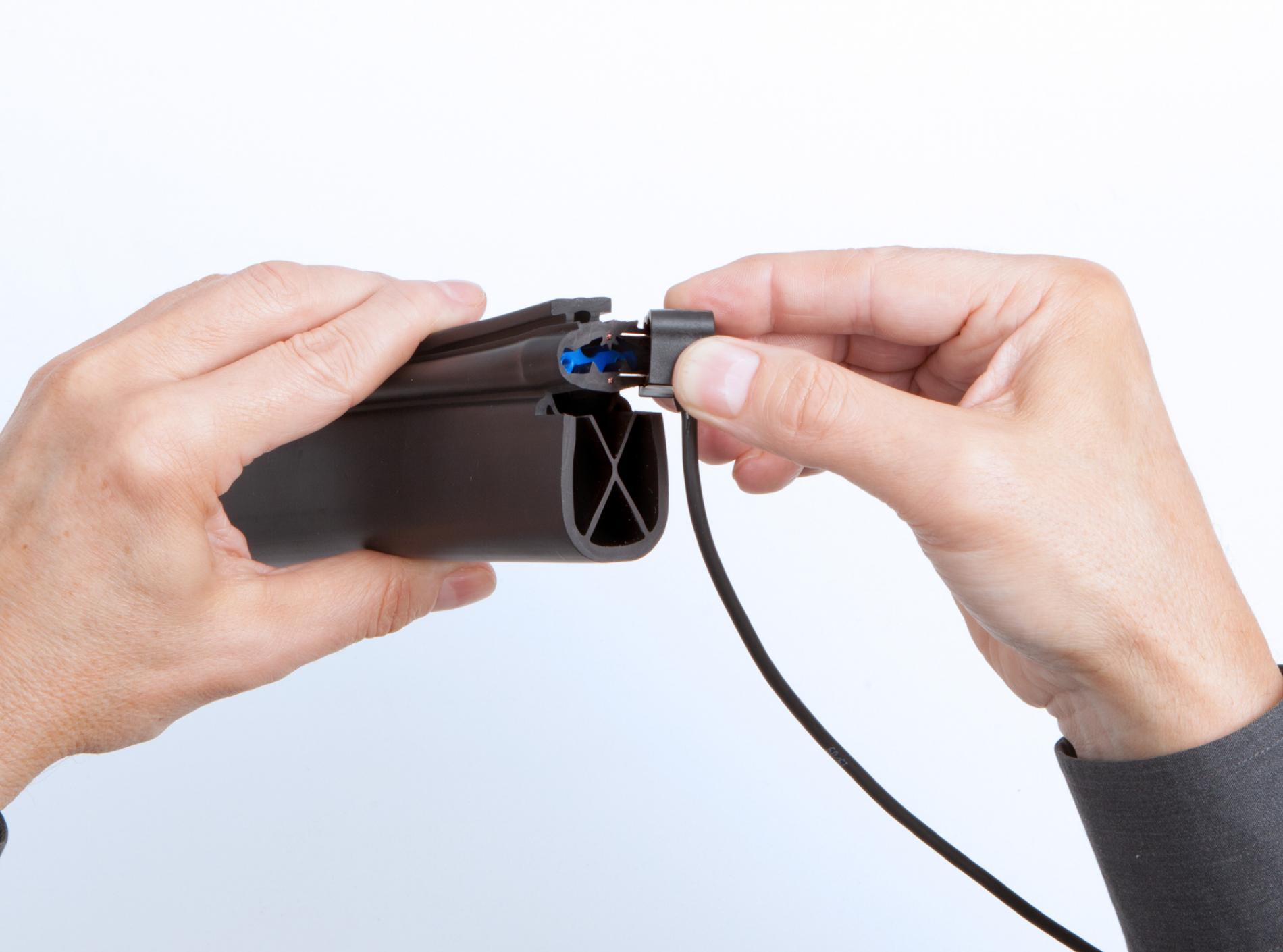
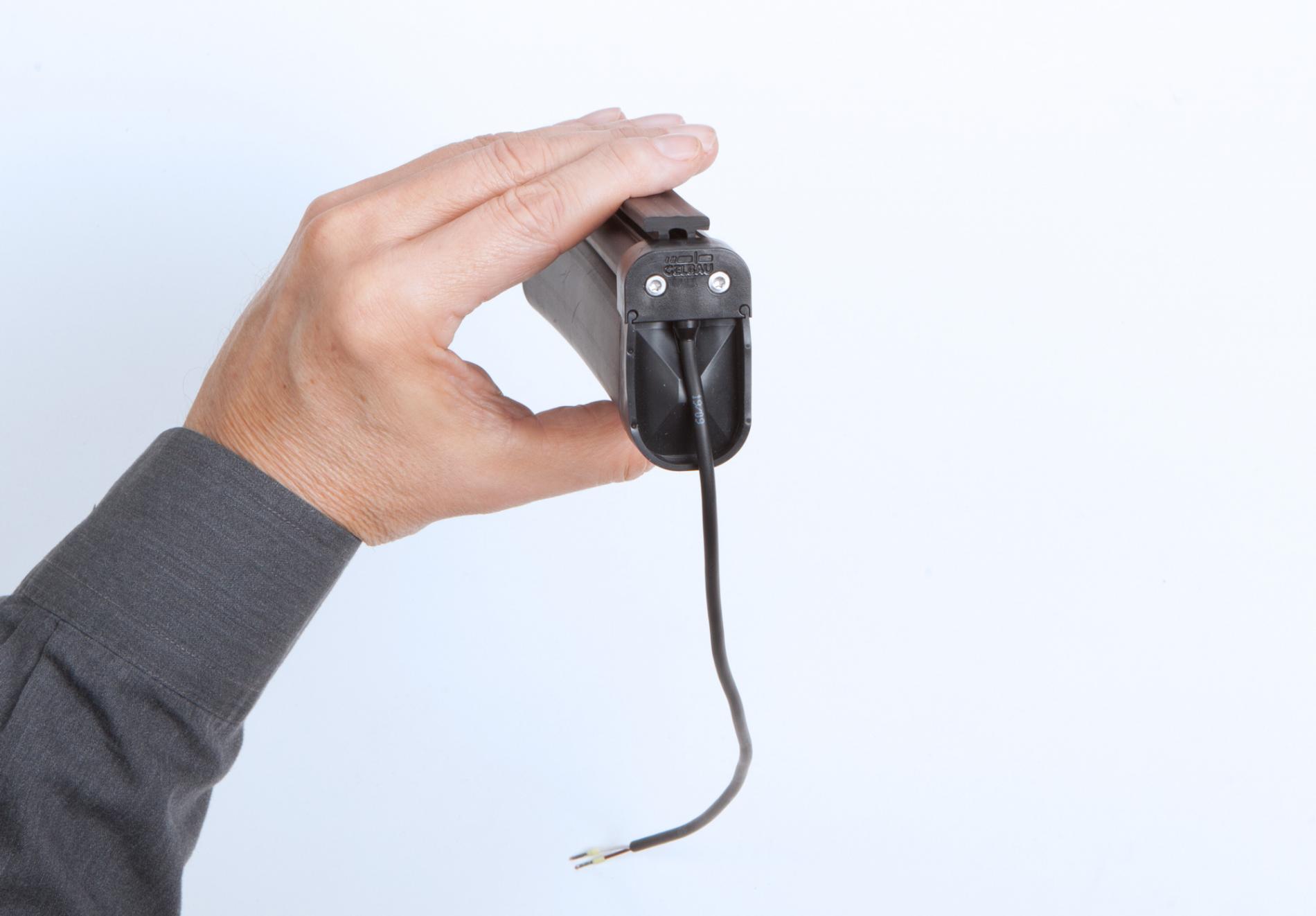
Note: The cap is properly installed when the two grooves on the outer edge of the cap point toward the compensation chamber. Inspecting the cap from the inside can also serve to verify proper installation: this shows the contour of the profile. The final result need not be a perfectly square fit.
7
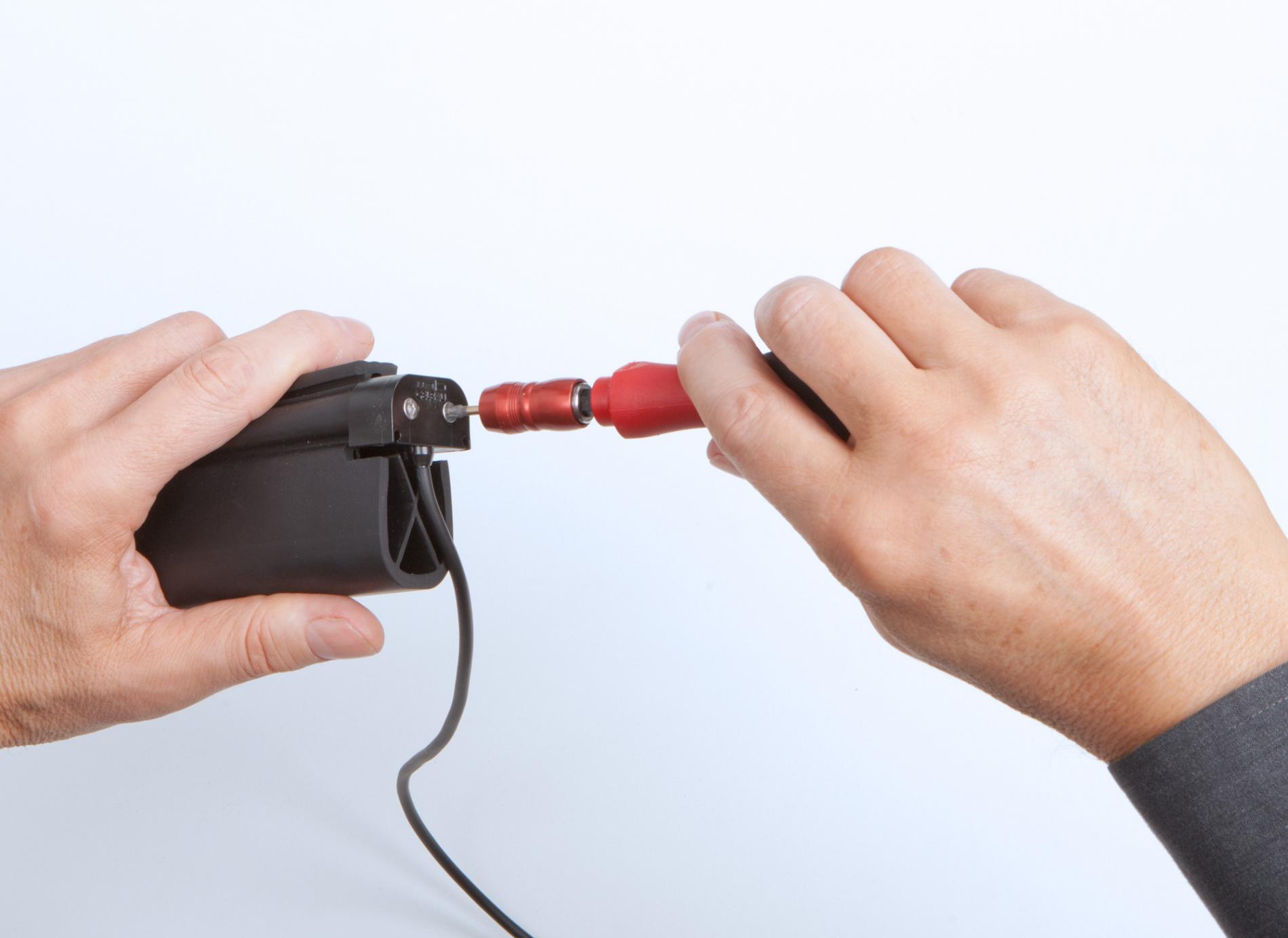
Making the crimp connection
Insert the screws into the corresponding holes of the end cap and tighten them gradually, alternating (!) iteratively. While tightening, you will notice that you are pulling the inner section, which is inserted further, into the outer cap. This forms the crimp connection. Keep tightening until you feel perceptible mechanical resistance.
8
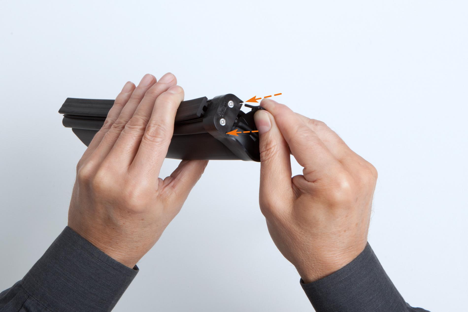
Fitting the rubber cap
Push the rubber cap (for closing the compensation chamber) into the grooves in the end cap of the switching chamber, and therefore onto the profile.
9
Gluing the rubber cap
Fold the circumferential edge of the rubber cap on the head of the profile and apply a thin film of adhesive to it. Fold the circumferential edge back into position and press the adhesion surface for approx. 10 seconds. Then prepare the right and left circumferential edges of the cap one after the other in the same way.
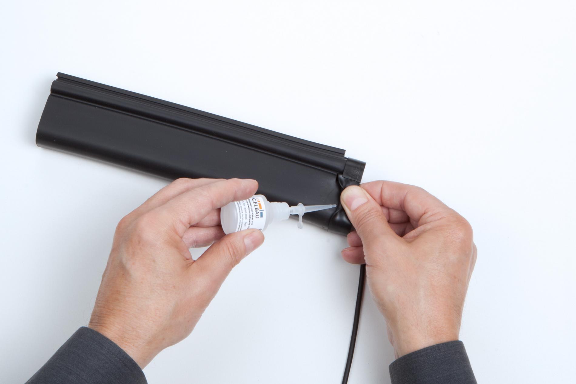
Note: With horizontally mounted safety strips, in order to ensure water drainage, use a Torx screwdriver to insert the rubber cap on the profile head. To improve adhesion, the profile can be slightly roughened beforehand.
To process the other side of the profile, repeat steps 2 to 9.